Project Description
Main Project Image
The project owner hasn't added main project image yet.
Project description
Bluetooth Low Energy Module
- Single Mode [just Bluetooth Low Energy communication protocol]
- Based on Nordic bluetooth chip nRF8001 (used in the Fitbit)
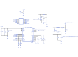
- Schematics based on the design reference from Nordic nRF8001 with internal DC/DC converter disabled.
- The internal low frequency (32.678kHz) crystal oscillator is used (optionally you can add and external crystal oscillator if high accuracy is needed, please check in nRF8001 documentation);
- The 50ohms impedance matching from the chip pins to the antenna was made using analog components based on Nordic design reference, but optionally you can use the Johanson 2450BM14A0002 Balun.
PCB considerations:
- 2 layers board
- 10 mils trace width for power and antenna traces;
- 6 mils for all other traces;
- 6 mils minimum clearance for copper to copper;
- Via with 13 mils hole and 7 mils annular ring;
- All vias below components have solder mask to prevent short circuit when reflowing/soldering SMD components;
- nRF8001 footprint based on Nordic reference design and documentation;
Antenna considerations:
- Be aware that the performance of the chip antenna (shown in the datasheet) was measured using a specific ground plane size and shape; in other words, the ground plane total area and shape modifies the antenna performance. Therefore, after integrating this PCB to your own design, consider building a prototype to test the antenna performance.
- It is important to keep the size of the antenna keepout and the feed point positioning/distance, please check the chip antenna datasheet.
- Alternatively, you can change the chip antenna to whatever you want/need (for instance - PCB pattern antenna or dipole antenna), just remember to match the impedances from the chip pins to the antenna, that usually is 50ohms
MODULE Pins description:
- 1 - VCC_3V3 - Power supply (1.9V - 3.6V). For low power operation details please see page 45 of the nRF8001 datasheet. In addition, if you want to consider to use the internal DC/DC converter, please see page 19 of the datasheet.
- 2 - GND (0V).
SPI interface (ACI - Application Controller Interface), for detailed information please see page 21 of the datasheet:
- 3 - BLE_SCK - Digital IN - SPI Serial data clock. ACI clock input. Must be high or low, not floating.
- 4 - BLE_MOSI - Digital IN - SPI Master Out, Slave In. Must be high or low, not floating.
- 5 - BLE_MISO - Digital OUT - SPI Master In Slave Out.
- 6 - BLE_RDYn - Digital OUT - ACI device ready indication (handshake signal, active low).
- 7 - BLE_REQn - Digital IN - ACI request pin (handshake signal, active low). Must be high or low, not floating.
UART interface (for detailed information, please see page 27 of the datasheet):
- 8 - TXD - Digital OUT - UART(transmit) for Bluetooth low energy Direct Test Mode interface (DTM). Leave unconnected if not in use.
- 9 - RXD - Digital IN - UART(receive) for Bluetooth low energy Direct Test Mode interface (DTM). Leave unconnected if not in use.
- 10 - BLE_ACTIVE - Digital OUT - Device RF front end activity indicator. It indicates that the nRF8001 radio is active. Its polarity can be configured active high or active low. (for detailed information, please see page 27 of the datasheet).
- 11 - BLE_RESETn - Digital IN - Reset(active low).
Technical documents/information about the nRF8001: http://www.nordicsemi.com/eng/Products/Bluetooth-R-low-energy/nRF8001
Gallery
The project owner hasn't added any images yet.
Design Files
Embed Code
Component (21)
Qty
Description
NRF8001-R2Q32-R
U1
1
nRF8001 µBlue™ Single-chip BLE
Capacitor
C23
1
Generic Capacitor (2.2nF)
2x5 female header
J103
1
10 (2x5) Pin Female Header
Capacitor
C18
1
Generic Capacitor (100nF)
