Project Description
Main Project Image
The project owner hasn't added main project image yet.
Project description
**Edit: the answers are below. This design has been fixed.
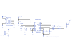
3 schematic errors:
1. CEn is tied to VCC_BAT. Should be tied to GND to enable charging.
2. EN2 is tied to GND. Should should be tied to VCC_5V_USB to allow the input current limit to be set by R8.
3. R9 is set to 72K. Should be 37.4K to set the fast charge safety timer to 5 hours.
4th bonus error on layout:
4. The dot on the silkscreens for D1 and D3 are on the wrong side. As a result, the LEDs will be installed backwards during manufacturing and they won't turn on. The industry standard is to have the dot on the side of the cathode
FUNCTIONAL SPEC
* The functional purpose of this design is to charge a battery from the USB connector that is connected to a 1.5A wall charger. This board also provides power to a load connected to VCC_SYS. Status is indicated by the LEDs. The battery is a standard LiPo with max voltage = 4.2V. A limit of 1.3A (+/- 20%) is imposed on the current drawn from the USB connector. A fast charge current of 800mA (+/- 10%) is imposed on the battery.
CHALLENGE DETAILS
* There are 3 errors in this schematic that will result in the board not working as specified above.
* Fork the design, open it in the editor, find the errors, and fix them on the schematic.
* Prizes: $25 Amazon Gift if you correctly fix all 3 schematic errors. Upped to $30 if you also make corresponding fixes to the layout and clear all Design Rule violations. Upped to $35 if you also find and fix the 4th bonus error on the layout (ie. the board will not fully function as specified if manufactured and assembled with the current layout. Hint: this error is obscure and you have to be a sharp HW design reviewer to spot it!)
HOW TO SUBMIT
Tweet us your Upverter username using this message: Hey @upverter, I'm and I completed your Schematic Review challenge. Now gimme my $25 Amazon gift card! https://upverter.com/anandh/e853f6e7605457a0/Design-Review-Challenge/
* Submissions will be accepted until Feb 26, 2015!
Gallery
The project owner hasn't added any images yet.
Design Files
Embed Code
Component (10)
Qty
Description
Resistor
R10, R9, R6, R8
4
Generic Resistor (1.13K)
ZX62-B-5PA(11)
J1
1
USB Micro B, SMT
Capacitor
C1
1
Generic Capacitor (1uF)
Capacitor
C5
1
Generic Capacitor (4.7uF)
