Project Description

Project description
Background
Currently an EE student, this is my second PCB design so far and the first with production in mind. The intent of this project is to better understand PCB design and manual trace routing.
Design
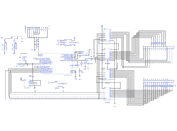
The SummerLights schematics are based on some pre-existing LED matrix controller schematics I've found. My implementation uses four shift registers and an ATMEGA328P-AU MCU to control a pre-built 8x8 RGB LED Matrix (Link Below). The shift registers are sent data serially from the MCU to control each of the 24 Cathode pins (8 Red, 8 Blue, 8 Green) and the 8 Common Anode Pins.
Hardware Features
In addition to the contoller, several convenience and harware add-on features were included in the design. FTDI and ICSP headers were provided for easier programming access. A footprint for connection to an LM35 was included to add temperature sensing. Through-holes were added for access to PB0, PB1, and PB2 for future expansion. Two programmable buttons are also included (Menu and Select) which are wired to PC0 and PC1.
Issues & Future Expansion
The current design should be functional. A smaller version of the board using all SMD components is desired. Cathode resistor values are subject to change depending on resulting brightness. Since transistors were not used to control the cathode/anode lines, brightness can't be modified once the resistors are installed since it is dependent on the shift register output current.
Gallery
External Links
Design Files
Embed Code
CFR-25JB-220R
R19, R20, R17, R8, R4, R26, R2, R24, R23, R11, R7, R18, R9, R21, R13, R12, R25, R5, R3, R14, R15, R16, R6, R22, R1
TL3301NF260QG
SW3, SW2, SW1
151033BS03000
D1
arduino icsp
J4
