
Project Description
Main Project Image
The project owner hasn't added main project image yet.
Project description
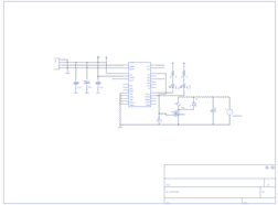
This is a basic breakout board for the FTDI FT232RL USB to serial IC. The pinout of this board matches the FTDI cable to work with official Arduino and cloned 5V Arduino boards. It can also be used for general serial applications. The major difference with this board is that it brings out the DTR pin as opposed to the RTS pin of the FTDI cable. The DTR pin allows an Arduino target to auto-reset when a new Sketch is downloaded. This is a really nice feature to have and allows a sketch to be downloaded without having to hit the reset button. This board will auto reset any Arduino board that has the reset pin brought out to a 6-pin connector.
The pins labeled BLK and GRN correspond to the colored wires on the . The black wire on the FTDI cable is GND, green is DTR. Use these BLK and GRN pins to align the FTDI basic board with your Arduino target.
There are pros and cons to the FTDI Cable vs the FTDI Basic. This board has TX and RX LEDs that allow you to actually see serial traffic on the LEDs to verify if the board is working, but this board requires a miniB cable. The FTDI Cable is well protected against the elements, but is large and cannot be embedded into a project as easily. The FTDI Basic uses DTR to cause a hardware reset where the FTDI cable uses the RTS signal.
This board was designed to decrease the cost of Arduino development and increase ease of use (the auto-reset feature rocks!). Our Arduino Pro boards and LilyPads use this type of connector.
One of the nice features of this board is a jumper on the back of the board that allows the board to be configured to either 3.3V or 5V (both power output and IO level). This board ship default to 5V, but you can cut the default trace and add a solder jumper if you need to switch to 3.3V.
Project description, more information and ordering can be found at https://www.sparkfun.com/products/10008
FTDI Drivers: http://www.google.com/url?sa=t&ct=res&cd=1&url=http%3A%2F%2Fwww.ftdichip.com%2FFTDrivers.htm&ei=D7WlSMGOJKOKiAGx-82BDQ&usg=AFQjCNE2pWdUmKFsw6OAb9hwsC8CtftzFQ&sig2=HQApwDh2F68V38PkMHy6jg
Gallery
The project owner hasn't added any images yet.
Design Files
Embed Code
Component (18)
Qty
Description
SparkFun:FRAME-LETTER:
FRAME1
1
SparkFun:FRAME-LETTER:
SparkFun:CAP:0402
C2, C1
2
SparkFun:CAP:0402
SparkFun:VCC:
P+1
1
SparkFun:VCC:
SparkFun:GND:
GND2, GND7, GND1, GND8, GND5
5
SparkFun:GND: