BenchSupply

Project Description
Main Project Image
The project owner hasn't added main project image yet.
Project description
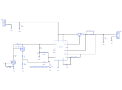
It has adjustable voltage limit but not adjustable current limit.
Some design notes:
Vin = 10-13.2V
Iin = 2.6A max
Vout (fixed) = 5.0V when R3 = 2.1k, R4 = 5k
When R4 wiper goes to GND side of R4, output goes to 0V.
When R4 wiper goes to high side of R4, output goes to VREF (~ 7.15V).
Vout (max, short circuit) = 2.6A
With R1||R2 = ~0.25 ohm, short circuit current limit is 0.65V/0.25ohm = 2.6A.
At Isc, R1 and R2 share ~1.7W, so 2W components provide 50% derating
At Isc, Q1 drops all of the input voltage except the 0.65V across the sense resistors, so worst case 13.2-0.65 = 32.6W, which is 60% of MJB44H11G's rated power.
Variable current limit control can be added by separately controlling ISENSE based on a variable gain on the output current sense voltage. Need multiple MJB44H11G's in parallel to achieve higher output current. Need current amplifier on U1 VOUT output to accommodate this.
Gallery
The project owner hasn't added any images yet.
Design Files
Embed Code
Component (15)
Qty
Description
Resistor
R15
1
Generic Resistor (1k)
LM723CN/NOPB
U1
1
Standard
MJB44H11T4G
Q1
1
Standard
Capacitor
C3
1
Generic Capacitor (1 uF)