8 Channel USB Logic Analyzer

Project Description
Main Project Image
The project owner hasn't added main project image yet.
Project description
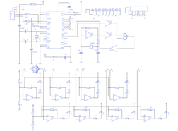
8 channel USB logic analyzer
============================
Logic analyzers are allowing us to monitor and/or diagnose a large number of digital signals simultaneously and these devices are
essential when developing complex digital systems. In this project we design simple 8 channel USB logic analyzer with Windows
version of driver software.
Design of this logic analyzer is based around Future Technology Devices FT245 USB FIFO chip. With the given oscillator this system
takes 14MSPS (Mega samples per second) and this system is design to work as (USB) self powered device (without any external power
source).
Driver part of this project is based on FTD2XX driver and GUI is developed using Delphi. Current version of driver software is
design to work with Windows NT operating systems and it is highly recommended to use it with 1360 x 768 or with higher video
resolutions (with aspect ratio of 16:9).
This design also contains real-time logic level indicators to monitor ìlow frequencyî signal levels and construction of that portion
is not much essential.
When constructing the circuit take special care about IC1 ñ 4069 Hex Inverter (in this design it mainly worked as CMOS
Pierce - Gate oscillator), because at the time of testing we found that some of the chips may not produce proper output and finally
it get affected to the entire system (including driver software). In our prototype we use Fairchildís CD4069UBCN as IC1.
All the project source codes, binaries, schematic diagrams and PCB patterns are available in with
terms and conditions of GNU GPL.
Files and Folders
=================
All the device drivers and other files are located at the root of the zip file.
Cryptographically Signed MD5 Checksum of usb8clgc.exe is 913586a0ce122c72899e1707b0b30cb6.
\Schematic folder contain all the schematic diagrams and PCB patterns in PNG and EAGLE Layout Editor formats.
\Source folder contain Delphi 7 source code of usb8clgc.exe file.
Contacts
========
Web : http://jayakody2000lk.wordpress.com
E-mail : jayakody2000lk@gmail.com
Gallery
The project owner hasn't added any images yet.
Design Files
Embed Code
Component (23)
Qty
Description
special:DRIL-2,5
2
special:DRIL-2,5
supply1:VCC:
P+6, P+12, P+3, P+1, P+8, P+9, P+10, P+11, P+5, P+2, P+13, P+4, P+7
13
supply1:VCC:
led:LED:5MM
LED1, LED6, LED9, LED4, LED7, LED8, LED3, LED5, LED2
9
led:LED:5MM
supply1:GND:
GND2, GND8, GND9, GND7, GND4, GND5, GND3, GND12, GND10, GND1, GND11, GND6
12
supply1:GND: