Replacement Code Lock for LS7220 base Systems

Project Description
Main Project Image
The project owner hasn't added main project image yet.
Project description
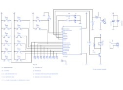
LSI Computer System’s LS7220 is a digital code lock system for automotive systems. This LS7220 integrated circuit is difficult to find in many places and because of that we design some alternative system which simulate the functionally of LS7220 code lock system. This simulated system executes on top of the PIC16F628A 8bit MCU and it release as an open hardware project.
LS7220 is a "hard-wired" code-locking system, but this simulated system provides both "hard-wired" and customizable (re-programmable) code locking options. This re-programmable feature provides some higher degree of protection to the system and it allows user/administrator to change system’s code at any given time by without changing the wiring layout(s) of the system.
In this project PIC16F628A MCU use its internal 4MHz oscillator and because of that it doesn’t require any external clocking source(s). This system is design to work with 5V DC power supply and its output is interface with 5V - 12V relay to drive the locking mechanism(s).
Compared with the LS7220 the only drawback of this system is its limited supply voltage. LS7220 have some wide supply voltage range like 5V - 18V DC. But still you can also couple this virtual system to that supply voltage by using some voltage regulation ICs like LM7805, LM317, etc.
The firmware of this system is written using Hi-Tech C and it is design with minimum external component dependencies. Because of that user can use "programmed MCU" with his/her own circuit design / customizations.
The main purpose of this project is to create some alternative design for LS7220 base code locking systems. Please note that this is not a project to degrade the features/specifications of LSI-CSI’s LS7220 (or related) products. All the content of this project are release under the terms of GNU GPL Version 3.0 license.
Gallery
The project owner hasn't added any images yet.
Design Files
Embed Code
Component (16)
Qty
Description
microchip:PIC16*F62:8P
IC1
1
microchip:PIC16*F62:8P
switch-omron:10-XX:
S1, S2, S3, S4, S5, S6, S7, S8, S9, S10, S11, S12, S13, S14
14
switch-omron:10-XX:
supply1:+5V:
P+1, P+2, P+3, P+4, P+6
5
supply1:+5V:
resistor-net:RNX8:
RN1
1
resistor-net:RNX8: