DIY Liquid Level Monitor and Automatic Control System

Project Description
Main Project Image
The project owner hasn't added main project image yet.
Project description
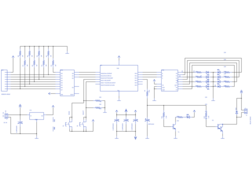
This is an easy to build "liquid level monitor" and "automatic control system". This control system is mainly based on Microchip’s PIC16F630 8bit MCU and few combinatorial logic ICs. This system is specifically design for industries where there is a requirement of maintaining a liquid level at a particular level. The level monitoring stage of this system can capable to sense up-to 8 liquid levels and its trigger point can be programmed at anytime by using its simple 2 button user-interface.
This system is design to work with 12V (or maximum of 25V) DC power source and its sensor system is capable of sensing liquids with resistance of up-to 30k to 35k. To minimize the sensor noise and output instability, the control software is equipped with simple 20-tap FIR like filter system.
The output stage of this system is design to work with 12V to 24V DC relays and it is recommended to use Tyco K10 series or similar kind of relay with this system.
The trigger point of this system is easy to define and it can be done by using S1 and S2 tactile switches. Once user press the S1 (MODE) switch the system enters into programming mode (and that stage trigger point LED starts to get blink), after that user can select desired trigger point by pressing the S2 (SELECT) switch continuously. Once new trigger point is set user can leave the programming mode by press S1 switch again.
The control software of this system is developed using Microchip’s Hi-Tech C compiler and it is available to download with GNU GPL license. This system consist with some sensitive CMOS ICs, so make sure to take necessary precautions while assembling and installing of this system (specially take care about the sensor probes).
As a sensor probes use any suitable low resistive conductor (e.g: copper or aluminum wire) and make sure that it is not reactive with the target liquid type.
This DIY "Liquid Level Monitor and Automatic Control System" is an open hardware project. All the design documents of this system are released under the terms Creative Commons Attribution 3.0 Unported License and firmware source code is release under the terms of GNU General Public License 3.0.
Gallery
The project owner hasn't added any images yet.
Design Files
Embed Code
Component (24)
Qty
Description
resistor:R-US_:0204/7
R20, R19, R14, R8, R22, R10, R11, R16, R6, R12, R21, R4, R5, R9, R13, R1, R3, R18, R15, R2, R17, R7
22
resistor:R-US_:0204/7
jumper:07
3
jumper:07
supply1:GND:
GND10, GND1, GND2, GND5, GND6, GND8, GND4, GND9, GND3, GND7
10
supply1:GND:
supply1:+5V:
P+3, P+2, P+1, P+6, P+9, P+8, P+5, P+4
8
supply1:+5V: