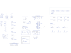
LPPC-Generic_Board-V2
Forked from
Known forks (1)
Tags
No License
Published: September 10, 2019 Complete
Project Description
Main Project Image
Project description
Gallery
Design Files

Embed Code
ERJ-PB6B5761V
M6:R8, M2:R8, M4:R7, M6:R7, M2:R7, M1:R7, M5:R7, M5:R8, M3:R7, M3:R8, M4:R8, M1:R8
1726040
J43, J46, J60, J44, J62, J63, J47, J53, J56, J57, J64, J51, J48, J52, J42, J45, J54, J59, J61, J41, J58
SMBJ6.5A-TR
M3:D2, M1:D2, M3:D1, M2:D2, M5:D2, M2:D1, M4:D2, M1:D1, M4:D1, M6:D1, M6:D2, M5:D1
Resistor
R26
Resistor
R40
RMCF0805JT1M00
M4:R3, M6:R4, M2:R3, M3:R3, M5:R4, M1:R4, M2:R4, M5:R3, M1:R3, M6:R3, M4:R4, M3:R4
Resistor
R48, R55, R50, R57, R53, R46, R49, R51, R56, R52, R54, R47
RMCF0805FT402R
M1:R2, M5:R1, M6:R2, M4:R1, M2:R2, M1:R1, M2:R1, M6:R1, M3:R2, M5:R2, M3:R1, M4:R2
1985865
J18, J38, J17
NRVTS260ESFT1G
D14, D16, D13, D18, D19, D17, D20, D21, D24, D15, D22, D23
EEE-FT1V561GP
C57, C58
EEE-HD1E4R7AR
C32, C33, C34, C40
TLP387
U530, U500, U524, U509, U515, U520
ERJ-PB6B3001V
M2:R6, M4:R5, M1:R5, M4:R6, M6:R6, M2:R5, M6:R5, M3:R5, M5:R5, M3:R6, M5:R6, M1:R6
LM2902KAVQD
M5:U1, M3:U1, M6:U1, M2:U1, M1:U1, U8, M4:U1
TM4C1294_LaunchPad
U37
Resistor
R37
SM712-02HTG
M7:U2, M13:U2
Capacitor
C48, C47
Capacitor
C45, C46, C44, C43
1985878
J4, J6, J5
Resistor
R39
Resistor
R68, R59, R64, R67, R61, R60, R69, R62, R58, R63, R65, R66
Capacitor
C42
Capacitor
C13
TLP3545A(LF1,TP1)
U486, U443, U479, U493
Resistor
R36
Resistor
R27
BC846ALT1G
Q7, Q5, Q2, Q3, Q6, Q4
Capacitor
C22
Capacitor
C25
Resistor
R30, R29, R34, R32, R35, R33, R28
Capacitor
C41
1985865
J2
SSR-LC
U320
PYB30-Q24-T512
PS36
Capacitor
M13:C1, M7:C1
DAC104S085CIMM/NOPB
U7
Capacitor
C10
Capacitor
C20
SMA6J6.5A
D8, D11, D6, D12
Capacitor
C21
Resistor
R44, R45, R42, R43
Resistor
M13:R5, M7:R5
Capacitor
C23
Resistor
R70
Resistor
M13:R4, M7:R4
TPSMB15CA
D3, D2
SN65HVD72D
M13:U1, M7:U1
Resistor
M13:R3, M7:R3
CRS0805-FX-10R0ELF
M7:R1, M7:R2, M13:R2, M13:R1
Capacitor
C26
UCW1C470MCL1GS
C67, C66, C65, C64
Capacitor
C11
C0805C104J1RACTU
M3:C1, M5:C1, M2:C1, M1:C1, M6:C1, M4:C1
Resistor
R31
Capacitor
C12
Resistor
R38
3568
F1
TRS3232EIDR
U42
Capacitor
C24
SLD15U-017
D5
DW-10-09-L-T-415
J39
SN65HVD1050AQDRQ1
U52
LM2902KAVQD
U379