
Project Description

Project description
The Maisken Homelay V1.0.1 is meant to provide access to a few ESP32 features that may be of interest for home automation projects. The project stems from the features offered by WiFi switches like the SONOFF, but tries to achieve the flexibility often required in DIY home automation projects.
Main goals
- The board must be powered with typical 110/220VAC
- Relays must provide dry contacts. That is, they are not linked to the 110/220VAC power supply, so that you can use them for example to trigger an event (e.g. temporarily close a switch to trigger a garage door to open), or power non-mains circuits (e.g. power a fountain pump or a watering solenoid with a separate 24VAC circuit), or of course, power a light bulb by connecting the relay to the mains
- Provide generic digital IO pins, so that you can drive 3V3 output, or define input binary sensors (e.g. a switch telling you if a door is open)
- Provide analog input pins, so that analog sensors (e.g. a soil moisture sensor) can be connected
- Provide an I2C interface to connect I2C sensors
- Be small, yet easy to assemble by an average-skilled soldering amateur
- Be safe (if you assemble it properly)
- As a plus for using ESP32, you also get Bluetooth support and a Hall sensor
How the goals are achieved
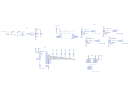
Maisken Homelay V1.0.1 offers up to four dry-contact relays that can be driven via the ESP32. Each realy offers NC and NO contacts, for the maximum flexibility in your application. On the board, they are called K1, K2, K3 and K4, driven by GPIO 16, 17, 18 and 19 respectively.
If you install a relay, it is recommended that you also install the corresponding pull-down resistor, marked as R_K1 through R_K4. A value of 10KOhm will work fine. Note that the ESP32 offers built-in, software activated pull-up and pull-down resistors. However, these cannot be controlled during boot, before your firmware takes control; hence installing an external pull-down resistor removes floating-pin issues at boot time, when the pin is input mode with no pull-up or pull-down resistor and an output value cannot be driven.
The relays are rated 10A at 220VAC: this is a lot of current. PCB traces joining the screw terminals to the relays should be too large to fit on the PCB; alternatively one may need to solder additional copper on top of the traces. Creating a small trace asking people to solder additional copper on top of it is asking for trouble, as many would just solder the components without adding the needed copper, see that "it works well"... until it burns. There is no trace between the NO, COM, and NC terminals of the relays and the screw terminals, there is just a silkscreen drawing instructing which pins need to be joined. You have to solder an external, 1.5mm-thick insulated electrical cable manually: this is intentional.
If you install the header J1, you get access to:
- GND, 3V3 and 5V pins
- Eight GPIOs (13, 14, 23, 25, 26, 27, 32, 33), of which two (32, 33) can also support an analog input
- Two input-only pins dedicated to analog inputs (34, 35)
- SDA and SCL pins for the I2C bus
If you plan using any of the eight GPIO pins as a binary input, just enable the ESP32 internal pull-up or pull-down resistor via software: this is sound since your firmware will not read the input value before the internal pull-up or pull-down resistor has been set up. If you plan using the pin as an output, the driven application may require a pull-up or pull-down resistor according to its specification. You'll need to make sure that the application being driven provides the adequate resistor on its board. All Maisken Homelay V1.0.1 available GPIO pins do not set any pull-up or pull-down resistor at start up, nor their value at boot influences the boot process of the ESP32, giving you the flexibility of installing the pull-up or pull-down resistor that your driven application needs.
For the I2C bus, the ESP32 offers built-in pull-up resistors of a fixed value; however, chosing the right pull-up value for your I2C bus features is a non-trivial task, and there is no value that will fit them all. Maisken Homelay V1.0.1 offers the possibility of installing external pull-up resistors of your choice, for the maximum flexibility in setting up your I2C bus. These resistors are named R_SDA and R_SCL. I2C buses are sensitive to inductances, which reduce the maximum bus cable lenght. Maisken Homelay V1.0.1 keeps I2C traces as thick as possible, to minimize such issues.
If you install the header J2, you also get access to:
- The RX and TX pins of the ESP32 board. This can be useful for debugging or flashing without using the USB port of the ESP32 board. It is not recommended to use these pins as GPIO, as they are pulled up at boot.
- K1 through K4 pins (GPIO 16, through 19 respectively), for an additional four GPIO pins. In this case, it is recommended to not install the K1 through K4 relays just to avoid confusion. If you do, you're expected to know what you're doing.
The board may get a bit packed with tall components on the top surface, but since all components are soldered through hole, the bottom surface should be clean enough to solder, even if you aren't the most experienced one. You do not need to solder each pin of the ESP32 DevKitC and the ULN2003A, because not all pins are used by Maisken Homelay V1.0.1; the pins of these components that need to be soldered to get the expected functionality are marked with a line on the bottom surface of the board, so this is visibile when you are soldering.
The mains circuit is isolated from the secondary circuit according to current best practices and standard recommendations. Namely, each mains trace is at least 4mm away from a secondary trace; and each mains trace is at least 2mm away from another mains trace. Additionally, the board has slots that further physically isolate the mains, and the relays circuitry, from the secondary circuits.
The HLK-PM01 power supply is instrumented with all recommended safety features, such as a current and a thermal fuse, a varistor and, on the 5V side, a couple of capacitors to stabilize the output signals. Capacitors are placed and connected in a way that they are always on the shortest path between the power source and any other component, to maximise their efficacy.
Why not all ESP32-DevKitC pins are exposed?
There are a few pins on the ESP32-DevKitC board that have been intentionally not broken out onto the main board, to avoid confusion or issues when they are used.
Namely, GPIOs 0, 2, 5, 12 and 15 are used for boot, so their value at boot time influences the boot process, making it impossible to flexibly chose external pull-down or pull-up resistors when such pins are used as output pins. The Internet is plenty of forums with people asking why their ESP32 chip won't boot just because of a pull-up resistor attached to one of such pins. Maisken Homelay V1.0.1 avoids these issues altogether leaving those pins alone. After all, you still get eight boot-issue free GPIOs on the J1 header, plus four additional ones on the J2 header if you don't need the realys.
GPIO 4 is pulled down at boot. Again, this would not give the required flexibility when using GPIO 4 as an output, so this has been kept out as well.
GPIOs 6, 7, 8, 9, 10 and 11, while exposed on the ESP32-DevKitC breakout, are in fact used to communicate with the internal flash on the chip, so they cannot be used for other purposes.
Finally, looking at the ESP32-DevKitC schematics, SENSOR_VP and SENSOR_VN are each connected to their repsective SENSOR_CAPP and SENSOR_CAPN pins with a capacitor. This makes SENSOR_VP and SENSOR_VN amenable for Low Noise Amplifier (LNA) usage, which is however undocumented and hardly supported; unfortunately, in this configuration such pins cannot be used as analog input pins. As such, they have not been broken out to the Maisken Homelay V1.0.1 main J1 header.
Changelog
- Maisken Homelay V1.0.1
- Minor layout improvements
- Make room for ESP32-devkitc USB connector
- Lower MOV
- Swap capacitors and I2C pull-up resistors
- Put thermal fuse closer to HLK-PM01
- Shorten I2C traces
- Make PCB case friendly
- Make room around center screw socket for easier case mounting
- Add castellated holes for easier case locking
- Make room for ESP32-devkitc USB connector
- Break out TX and RX pins of the ESP32-devkitc
- Minor layout improvements
- Maisken Homelay V1.0
- Initial release
Gallery
Design Files
Embed Code
Capacitor
C2
Resistor
R_SDA
SRD-05VDC-SL-C
K1, K2, K4, K3
Polarized Capacitor
C1