
Project Description
Main Project Image
The project owner hasn't added main project image yet.
Project description
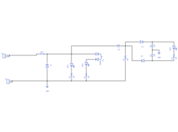
Inputs: Signal and Common
Outputs: 3.3V LED (on if signal >=3V)
5V LED (on if signal >=4.7V)
Data LED (on if signal frequency >50kHz)
The circuit has basic overvoltage protection. It is designed to be used as a bare PCB with no enclosure. Multiple headers provided for connection flexibility.
Gallery
The project owner hasn't added any images yet.
Design Files
Embed Code
Component (11)
Qty
Description
2 pin header (non-polarised)
J2, J1
2
2 pin header, 0.1" / 2.54mm pitch, through-hole
Resistor
R1, R4
2
Generic Resistor (220)
APTR3216SURCK
LED3, LED2, LED1
3
LED Reverse Mount
SMAJ6.0A-TR
Z1
1
Standard