Project Description
Main Project Image
The project owner hasn't added main project image yet.
Project description
SPECIFICATIONS
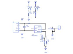
- User selectable charge rate -- 100mA or 500mA
- LED shows charging state; it turns on when charging is complete
COMPONENTS
- C1 and C2 are ceramic multi-layer capacitors, but they can be replaced with electrolytics for better capacitance (ceramic voltage coefficient means that they will only be 3-3.5 uF instead of 4.7 at 5V).
- J1 (3-way male header) should be shorted between pin 2 & 3 for 100mA of charging current and 1 & 2 for 500mA of current.
- R3 and R2 determine the charge current depending on which of the two is selected from J1. The equation for charge current can be found in the MCP73831 datasheet.
USAGE
- You can plug the charger into a 5V USB port or solder wires to the exposed USB pads for power.
- Setting the charge current selection jumper towards the blue blob on the header silkscreen sets it to 500mA.
- Removing the charge current selection jumper terminates the current charge (if one is active).
Gallery
The project owner hasn't added any images yet.
Design Files
Embed Code
Component (12)
Qty
Description
S2B-PH-SM4-TB(LF)(SN)
J2
1
S2B-PH-SM4-TB(LF)(SN)
Capacitor
C2
1
Generic Capacitor (4.7uF)
Resistor
R2
1
Generic Resistor (2k)
Resistor
R4
1
Generic Resistor (470r)
