
Project Description
Main Project Image
The project owner hasn't added main project image yet.
Project description
SPECIFICATIONS
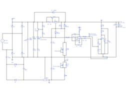
- Voltage output: 0V (min, trimmable between approximately -200mV and 200mV) to 15V (max, fixed)
- Current output: 0mA (min) to 1500mA (max, determined by max current limit)
- Current limit: 0mA (min) to 1500mA (max, fixed)
- Input: 15V RMS AC (50 - 60 Hz) at 2A
COMPONENTS
- Unlabelled diodes are 1N4001s.
- The max voltage and min voltage potentiometers should be trimmers.
- The voltage adjust and current limit adjust potentiometers should be multi-turn wirewound potentiometers (for increased accuracy when adjusting, these pots dissipate negligible heat so heat dissipation is not an issue).
- The 1.8 ohm resistor before the LM317 input should be at least 2W as it could have at least an amp going through it.
USAGE
- The input should be from a (minimum) 30VA transformer (15V RMS @ 2A).
- As the output is mains-isolated, multiple supplies can be multiplexed (as long as they are from separate transformer windings / separate transformers). Supplies can be configured in parallel to provide a higher maximum current or in series to provide a higher maximum voltage (or some combination thereof).
- If the supply(s) are mounted in an enclosure, all metal parts of the chassis MUST be mains earth grounded. Failure to do this could result in serious injury or death, as if a live conductor comes into contact with a non-earthed chassis the chassis will be live, and touching it will allow the mains current to pass through your body to earth. In contrast, if a live conductor comes into contact with an earthed chassis, the tripswitch controlling that section of your building's AC supply will blow and the circuit will remain safe (disabled).
- Use a fused IEC input connector, preferably with a built in 2P1T switch (so that when the switch is off both live and neutral are disconnected from the circuit), for the mains input.
- Use suitably wide internal hook-up wires to carry the maximum current (to be on the safe side, all internal hook-up wires should have an ampacity of AT LEAST 2A).
- Make sure all devices which dissipate a large amount of heat (LM317 and the power transistor) are connected to a suitable heatsink. The size of the heatsink may limit the maximum current output if it is too small.
Gallery
The project owner hasn't added any images yet.
Design Files
Embed Code
Component (48)
Qty
Description
Resistor
R19
1
Generic Resistor (9k1)
Resistor
R14
1
Generic Resistor (100r)
1N4001
D5
1
Generic Diode
BC557
Q2
1
Generic BJT (PNP)