BMC64 Joystick and Keyboard PCB - V3

Project Description

Project description
This PCB is designed to be used with BMC64 (a bare metal Commodore 64 emulator for the Rasbperry Pi 2/3) to get your 'C64 emulator in a C64 shell' project one step closer to perfection!
Use GPIO Config #2 in the menu.
BMC64 v2.4 or higher must be used (available at https://github.com/randyrossi/bmc64).
Note, this PCB will only work with BMC64 (or BMC128/BMVIC20 sister projects). It allows the emulator running on the Rasbperry Pi 2/3 to scan a real C64 keyboard and joysticks via GPIO. It also gives you switchable power in the same spot as the real C64. (NOTE: There are no analog inputs on the joystick ports, so paddles won't work.)
PCBWay will fabricate this board correctly from the gerber files. OshPark will not. I haven't tried other vendors or formats. This is meant to be a proof-of-concept board and I don't intend on fabricating them myself or selling them. My hope is someone will take the design and improve it. There are probably lots of things that can be done to make it less expensive.
Also, please keep in mind there is no ESD (Electro Static Discharge) protection circuitry on this board. So take care to ground yourself before touching the joystick port pins or a charge could damage your GPIO pins. (This was a problem on the real C64s BTW!)
This is a do-it-yourself project that involves soldering. Remember to remove the four lock bolts from the DB9 connectors or it will not slide through the side plate! (See pic) Mounting the PCB inside a breadbin style case is relatively straight forward.
Mounting the PCB inside a C64-C model case requires 3D printed brackets available here: https://www.thingiverse.com/thing:3051450 You need a right hand bracket that hangs over the two ribbon cable connectors and gives enough room for them to be connected without pushing up on the bracket. The other types of brackets meant for the Keyrah are not suitable as the right support is obstructed by the headers/cables. I also recommend printing a couple of these small supports to clip on the 'free' edge of the PCB to give it some support: https://www.thingiverse.com/thing:2882274
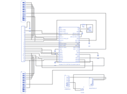
Ignore the parts list from Upverter. This is the real parts list using digikey parts:
1x 609-4965-ND USB Female Receptacle
2x 151-1292-ND DB9 Male Ports (Remember to remove the bolts!)
1x S2012EC-20-ND 40 Pin Header
1x S1212EC-20-ND 20 Pin Header
1x CP-202A-ND PWR JACK 2X5.5MM KINKED PIN
1x 360-4016-ND SWITCH ROCKER DPDT 6A 125V
1x 390 Ohm Resistor
+ 1 more 3 pin Header for the LED connector
You will also need a 40 Pin IDC cable to connect the 40 pin header of the Pi to the PCB. Something like H3CCS-4018G-ND, however keep in mind 6" may be too short depending on where you mount your Pi inside the C64 shell. You may want to get a longer one or build your own. Also, make sure you use a 40 conductor cable and NOT an 80 conductor cable.
To install this in your C64 shell:
1. Mount the PCB on the right side of the case, fitting the joystick and switch through the holes. On a 64-C case, there is no side plate required. On a breadbin, you need to mount the side plate underneath the PCB in the same way you do with a real motherboard. There are holes in the PCB that will let you do that in two spots.
2. Connect a standard USB power cable from the female connector on the PCB to the Pi.
3. Connect the 40 Pin IDC cable between the Pi's 40 pin header and the PCB's 40 pin header. See photo for correct orientation.
4. Connect your C64 keyboard to the keyboard connector on the PCB.
5. Connect the C64 shell's power LED to the power LED connector on the PCB.
6. In Prefs menu of BMC64, set GPIO Configuration to '#2 Keyboard/Joysticks'.
Switchable power is optional, so you could eliminate the power jack, switch and female USB all together. This would reduce the cost significantly. In that case, just plug power directly into your Pi as usual. If you do use power, you will need a 5V 2.5Amp power adapter with 2.10mm ID, 5.50mm OD barrel jack connector(something like 102-3425-ND). Make sure the power jack has a positive inner pin! Switching polarity will likely blow your Pi.
NOTE: You should not run anything but BMC64 while your Pi is connected to this PCB. It is possible other programs could set some GPIO pins to Output 3.3V in HI/LO combinations. Pressing keys or using the joystick could thus cause a short with no resistance to limit current and the pins could be blown.
Gallery
External Links
Design Files
Embed Code
Raspberry Pi B+ GPIO Male Shrouded Header RR
J4
M2022TXW41-FA
J8
3 Pin Header
J5
621-009-260-043
J1, J2