Button Pad 2x2 - Breakout PCB
Project Description
Main Project Image
The project owner hasn't added main project image yet.
Project description
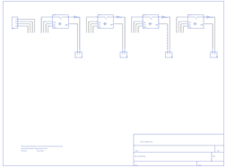
This a simple breakout board for the button pads. Each LED and button is brought out to the side connectors. The connectors are soldered to the back side of the PCB. We recommend trimming the connector leads on the button side as short as possible to reduce the deflection of the pad.
Project description, more information and ordering can be found at https://www.sparkfun.com/products/9277
Gallery
The project owner hasn't added any images yet.
Design Files
Embed Code
Component (7)
Qty
Description
SparkFun:DIODE-1N4148:
D5, D13, D2, D1
4
SparkFun:DIODE-1N4148:
SparkFun:BUTTONPAD-2X2:
P3
1
SparkFun:BUTTONPAD-2X2:
SparkFun:LOGO-SFE:NEW
U$1
1
SparkFun:LOGO-SFE:NEW
SparkFun:M02:POLAR
JP7, JP6, JP5, JP8
4
SparkFun:M02:POLAR