Breadboard Power Kit - Retail
Project Description
Main Project Image
The project owner hasn't added main project image yet.
Project description
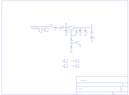
Here is a very simple breadboard power supply kit that takes power from a DC wall wart and outputs a selectable 5V or 3.3V regulated voltage. The .1" headers are mounted on the bottom of the PCB for simple insertion into a breadboard. Pins labeled VCC and GND plug directly into the power lines. The lone pair of pins have no electrical connection but help support the PCB.
Project description, more information and ordering can be found at https://www.sparkfun.com/products/10777
Quickstart Guide: http://www.sparkfun.com/tutorials/297
Gallery
The project owner hasn't added any images yet.
Design Files
Embed Code
Component (16)
Qty
Description
frames:LETTER_L:
FRAME1
1
frames:LETTER_L:
SparkFun:SWITCH-SPST:PTH
S1, S2
2
SparkFun:SWITCH-SPST:PTH
SparkFun:RESISTOR:PTH1
R2, R1, R4, R3
4
SparkFun:RESISTOR:PTH1
SparkFun:CAP_POL:PTH1
C1
1
SparkFun:CAP_POL:PTH1