
Project Description
Main Project Image
The project owner hasn't added main project image yet.
Project description
Design Title: MicroHeart
Description: A small Analog Front End [AD8232 from Analog Devices] to capture single LEAD ECG [Electro Cardiogram - heart activity] and monitor Heart Beat rate.
Purpose: Analog ECG output can be captured by ADC module and displayed onto TFT display. Heart Beat rate can be calculated from QRS complex.
Designed by: Kamrul Hussain
Main Chip: AD8232
Datasheet: http://www.analog.com/media/en/technical-documentation/data-sheets/AD8232.pdf
Category: Portable Healthcare Device [non-diagnostic]
Platform: Mikrobus Addon board [M]
Output pins: Analog -> [O/P] single Lead raw ECG signal - Digital-> [LO- and LO+] detection of electrode displacement from the body
Input pin: Digital -> [SDN] shuts down the AFE AD8232 module
Operating voltage: 3.3v
Safety issues: isolated power supply [IEC 60601-1 standard] or battery should be used
Prospects: Elementary project in Biomedical Electronics, Small form factor, Low power operation, Cost effective solution
Optional: The same board can be used as EMG [muscle activity] device by modifying the cut-off frequency of the filter ckt [i.e. a pair of resistance and capacitance]
Demonstration: A demo video can be found in the following link. Video demonstrates the capture of ECG using AD8232 AFE and display using Mikromedia for dsPIC33EP. Heart Beat rate was also calculated. The hardware demonstration starts at 2:30.
http://www.element14.com/community/videos/16003/l/ecg-heart-rate
BOM price: approximately 11 - 12 USD
Note:
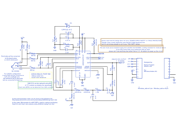
This design utilizes the AFE from ANALOG DEVICES, AD8232 to produce a single LEAD ECG analog output. It's a tiny module with high CMRR and integrated RLD [right leg drive] with additional active filters for signal conditioning. A LEAD off can be detected through LO- and LO+ pins and the module can be shut down using the SDN pin. All these input output pins are externally accessible using a microcontroller.
This entire module with passive components are placed in a Mikrobus Addon board layout and can be powered up with 3.3v. A reference voltage of 1.5v is internally generated by the module. The board contains a 3.5mm stereo jack to connect the 3 electrodes coming from the Body [Right arm, Left arm and Right leg].
The PCB has been designed carefully to accommodate all the components on TOP layer and use the BOTTOM layer as GND and REF plane for noise immunity. REF plane is poured tracking the analog input and conditioning ckt, where the GND plane is covering the digital i/o and other part of the module itself. Output has a voltage swing from 0 - 3v with 'FAST RECOVERY' and 'DC LEAD OFF' enabled.
PLEASE use an isolated supply [IEC60601-1 standard] or Battery to power up the board.
Gallery
The project owner hasn't added any images yet.
Design Files
Embed Code
Component (18)
Qty
Description