Project Description
Main Project Image
The project owner hasn't added main project image yet.
Project description
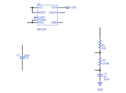
This is a PCB implementation of an NE555P timer chip, designed to have a near 50% duty cycle while performing in Astable Operation.
Gallery
The project owner hasn't added any images yet.
Design Files
Embed Code
Component (5)
Qty
Description
Resistor
R2
1
Generic Resistor (14.4K)
Capacitor
C2
1
Generic Capacitor (Non-Polarized) (10uF)
Resistor
R1
1
Generic Resistor (100)
NE555P
U1
1
555 Type, Timer/Oscillator (Single) IC 100kHz 8-DIP (0.300", 7.62mm)