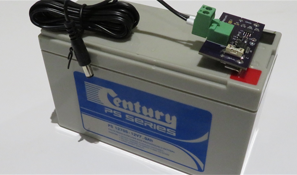
12V 7Ah SLA Low Voltage Disconnect

Project Description
Project description
The 12V 7Ahr "alarm" battery is still a safe, dependable choice for stationary back-up supplies, running items such as LED lighting or modem/routers.
Using two Keystone 3571 female PCB terminals, this PCB assembly attaches directly to the terminals of a 12V 7AH SLA Battery (with 4.75mm spade terminals) and provides a low voltage cut-out to protect the battery, and a fuse.
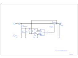
The Maxim Integrated MAX8212 Micro-power Voltage Comparator with 1.15V reference switches a high side P-Channel MOSFET to disconnect the load. The MOSFET has a low on resistance of 4.1mOhms and a maximum current capability of 90 Amps well exceeding that of the battery.
The MAX8212 can operate with a programmable threshold and hysteresis (Populate R3/R6/R7) ensuring the load doesn't oscillate when the low voltage trip point is reached and the battery terminal voltage rises. However, if this behaviour is not desirable, this circuit also allows the low voltage event to be latched by populating R4/S1/R7 instead, as per Maxim Application Note 926.
When the load is switched off, the MAX8212's 5uA quiescent current and the 11.2uA load of the voltage divider ensures the battery is not discharged.
The 102k/953k/86.6k voltage divider sets a low voltage cut-out at 11.9V and a reset high threshold of 12.87V.
Three printed circuit boards fabricated by OSH Park costs $11.15 and the BOM cost is approximately $12.15 from Digi-key.
Release Notes
|
1.A.1 |
30th April 2017 |
Prototype board sent to manufacture. |
|
1.A.2 |
30th May 2017 |
Despite detailed description above referring to MAX8212, schematic incorrectly referred MAX8211. Changed U1 to MAX8212. No changes made to PCB. |
|
1.A.3 |
1st July 2017 |
Rotated Keystone 3571 connectors J1 and J3. While both orientations work, this provides the flat face to help slide on the board. Replaced R1 with a low forward voltage drop Schottky Diode to provide reverse voltage protection to the board. The voltage drop of the Diode will need to be considered in voltage threshold calculations. If a low current Diode is fitted, C3 (10uF) should be removed, otherwise inrush currents can destroy the diode. Please note this will not protect the load, as the body diode of the MOSFET will conduct. |
Gallery
Design Files
Embed Code
OptiMOS-P2 Power-Transistor, -30 V VDS, -90 A ID, PG-TO252-3-11, Reel, Green
Q1
1757242
J2
CAP CER 10UF 35V 10% X5R 1206
C3
CAP CER 0.1UF 50V Y5V 0805
C1