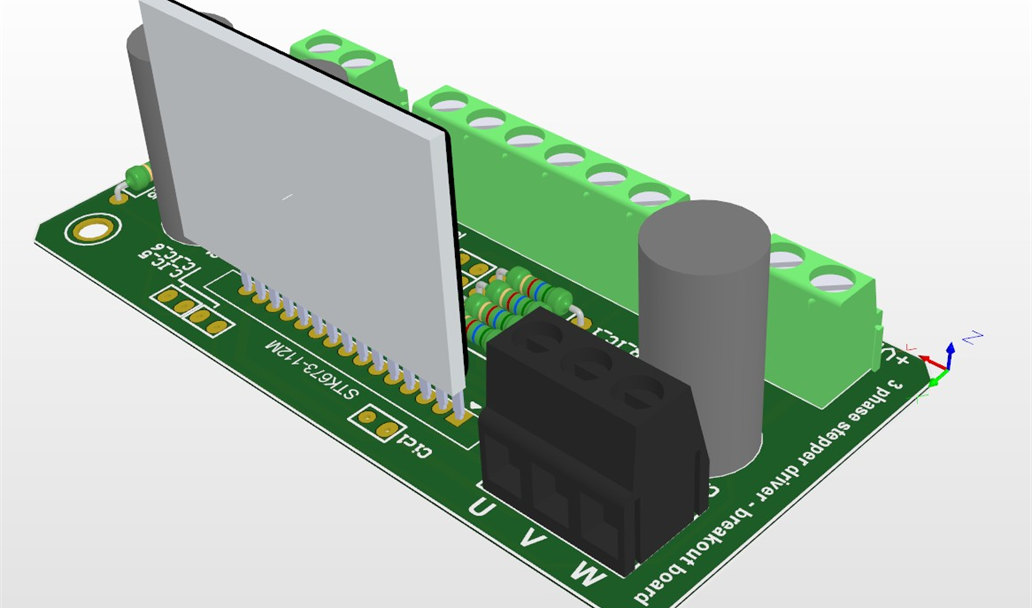
STK673-112M 3 phase stepper driver testing board

Project Description
Project description
This project was based on reusing parts of an old copy machine.
It just so happened to be using 3-phase stepper motors and 3-phase stepper motor drivers.
Since there was no datasheet for the drivers (STK673-112M), I had to follow the existing PCB where they were on ... measure and see what was connected to it. I also tried remaking the existing footprint of the 3-phase drivers.
In any case, as soon as I get to test the driver and try out what works best, I'll update this accordingly for others to use. As there are (to my knoweldege) no datasheets for this device, it'll be usefull to at least some of those people who "just so happened" to have these drivers lying around and trying to make use of them.
My remade footprint should be enough for testing and playing around.
Update (21. october 2016):
~SUCCESS
The circuit is working.
From practical tests and observation I was able to reverse engineer all except one Pin (11). When there is more time for testing I'll be updating the information on here.
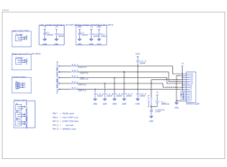
As it stands the control circuit is straight forward. All inputs seem to be triggered by grounding (aka INVERTED LOGIC).
When testing, the stepper motor I've driven was a 3-phase NEMA23 (not two)(worth 22€) with an Arduino Nano as controller and an amateur 0.5A 12V power supply. None-the-less the results were positive.
Some basic information I gathered during rought tests:
-The pins PULSE and DIRECTION are inverted, grounding them will trigger them.
-The ENABLE pin is negated (& inverted), grounding it will disable the output to the stepper motor.
-The HALF-STEP pin is OFF when grounding it (making a classic full-step per PULSE), otherwise leaving it HIGH will do what the pin name says.
-The metal case of the STK driver heats up pretty fast when trying to drive a NEMA 23 type 3-phase stepper motor, specially when trying to hold its position. Luckily the case dissipates heat very well, even just putting my fingers against it it cools down very fast which means a simple heatsink design should get the job done
-I'm not sure but I expect the maximum current to be 2A (or 3A) MAX (with heatsink, thermal paste and fan), will try and see when I have spare time
-From the tests/experiments I can safely assume the STK driver is compatible as an alternative to/replacement for the 2-phase pololu stepper drivers commonly used on 3D printers and hobby CNC machines (not exactly drop-in replacement, because one can't simply stick this thing in the socket)
I'll also be making a simpler circuit design with more optimised components and position, still keeping it on a single layer. Thinking of making a cut out for the STK on the board and make it lie down with a heatsink on the bottom ... but that will take a bit for me to get back to this side project, in the meantime there's studies and "student life" going on, so stay tuned ...
Gallery
Design Files
Embed Code
EEU-FC1V471
C1, C2
3-phase stepper driver
POWER_OBJECT
K104M15X7RF53L2
Cmcu, C_IC_1, C_IC_2, C_IC_3, Cic1, C_IC_4, C_IC_5, C_IC_6, Cic2