Automatic temperature speed controller for cooling fan

Project Description
Main Project Image
Project description
This circuit is practical to enable a automatic cooling to a system, it can be built entirely from savaged parts that should be very easy to obtain, not even a thermissor or temperature sensor is used.
PCB layout is included, but It should also be very easy to build this on a perf board.
This circuit was built and tested.
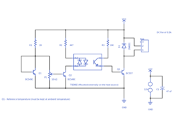
It works by monitoring a temperature of a heat source (e.g. heat sink) and automatically controlling the speed of a DC Fan. The circuit measures temperature difference by comparing a voltage drop of a transistor (Q1) with a base-emitter of a hot transistor Q2 (TSENSE). The transistor Q1 is used as a reference temperature, and it must be positioned away from the heat source to ensure that it is kept at ambient temperature.
The transistor Q2 TSENSE is mounted externally and must be thermally bounded to the heat source (e.g. use thermal paste and clamp it to a heat sink for example). Q2 should not conduct when the temperature monitored is below a set threshold (P1), the base-emitter voltage of Q2 decrease by 2mV per degree C. Once the voltage is below the level set by P1. Q2 starts to conduct and the fan starts to spin up. The speed of the fan increase as the temperature increases in a linear fashion. The absolute maximum temperature is 150ºC.
BC547 or other small signal NPN transistors can be used as a replacement for Q1 and Q2, the pair needs to be identical.
Replace Q3 with the appropriated ratings, if you're planning to use it with a larger or more than one cooler fan. Some alternatives are BD135 or a darlington TIP120/122 (a darlington transistor will ramp up to full RPM speed more quickly due to higher gain).
NOTE: This circuit is not suitable for battery operated devices as it is not very power efficient at controling the fan in linear mode. The advantage of that design is that it doesn't introduce EMF interference* in the power rail like PWM controllers, and is is a great way to add active cooling to audio devices like audio amplifiers.
* Even tho this circuit doens't add interference the fan used might introduce its own interference, in that case it is recommended to add a filter to the input in order to decouple the noise.
Gallery
Design Files
Embed Code
Resistor
R3
BC549C
Q2
ESH476M035AE3AA
C1
1N4001
D1