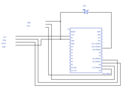
Project Description
Main Project Image
The project owner hasn't added main project image yet.
Project description
const int trigPin = 5;
const int echoPin = 4;
//const int ledPin = 7;
int flag = 0;
int brightness = 256; // how bright the LED is
int fadeAmount = 4; // how many points to fade the LED by
int led = 9;
#define RTS_pin 2 // RTS line for C17A - DB9 pin 7
#define DTR_pin 3 // DTR line for C17A - DB9 pin 4
#define BIT_DELAY 1 // ms delay between bits (0.5ms min.)
#define ON 0 // command for ON
#define OFF 1 // command for OFF
#define BRIGHT 2 // command for 20% brighten
#define DIM 3 // command for 20% dim
unsigned int houseCode[16] = {
0x6000, // A
0x7000, // B
0x4000, // C
0x5000, // D
0x8000, // E
0x9000, // F
0xA000, // G
0xB000, // H
0xE000, // I
0xF000, // J
0xC000, // K
0xD000, // L
0x0000, // M
0x1000, // N
0x2000, // O
0x3000, // P
};
unsigned int deviceCode[16] = {
0x0000, // 1
0x0010, // 2
0x0008, // 3
0x0018, // 4
0x0040, // 5
0x0050, // 6
0x0048, // 7
0x0058, // 8
0x0400, // 9
0x0410, // 10
0x0408, // 11
0x0418, // 12
0x0440, // 13
0x0450, // 14
0x0448, // 15
0x0458, // 16
};
unsigned int cmndCode[] = {
0x0000, // ON
0x0020, // OFF
0x0088, // 20% BRIGHT (0x00A8=5%)
0x0098, // 20% DIM (0x00B8=5%)
};
void setup() {
// initialize serial communication:
Serial.begin(9600);
pinMode(RTS_pin,OUTPUT); // onboard LED
pinMode(DTR_pin,OUTPUT); // output pin of touch sensor
//pinMode(ledPin,OUTPUT);
pinMode(led,OUTPUT);
}
void loop()
{
//delay(2000);
//xmitCM17A('M',7,ON);
//xmitCM17A('M',7,OFF);
//xmitCM17A('M',7,ON);
//xmitCM17A('M',7,DIM);
//xmitCM17A('D',5,DIM);
//xmitCM17A('D',5,DIM);
//xmitCM17A('D',5,DIM);
//xmitCM17A('D',5,DIM);
//xmitCM17A('D',5,OFF);
//xmitCM17A('D',4,ON);
// establish variables for duration of the ping,
// and the distance result in inches and centimeters:
long duration, inches, cm;
pinMode(trigPin, OUTPUT);
digitalWrite(trigPin, LOW);
delayMicroseconds(2);
digitalWrite(trigPin, HIGH);
delayMicroseconds(10);
digitalWrite(trigPin, LOW);
pinMode(echoPin, INPUT);
duration = pulseIn(echoPin, HIGH);
inches = microsecondsToInches(duration);
cm = microsecondsToCentimeters(duration);
if (cm < 10 && flag == 0)
{
brightness = 256;
Serial.print(brightness);
Serial.println();
xmitCM17A('M',7,ON);
flag = 1;
do
{
brightness = brightness - fadeAmount;
analogWrite(led, brightness);
Serial.print(brightness);
Serial.println();
delay(40);
}
while(brightness > 0);
}
else {
if (cm < 10 && flag == 1)
{
brightness = 256;
Serial.print(brightness);
Serial.println();
xmitCM17A('M',7,OFF);
flag = 0;
do
{
analogWrite(led, brightness);
brightness = brightness - fadeAmount;
Serial.print(brightness);
Serial.println();
delay(40);
}
while(brightness > -1);
}
}
delay(100);
}
long microsecondsToInches(long microseconds)
{
return microseconds / 74 / 2;
}
long microsecondsToCentimeters(long microseconds)
{
return microseconds / 29 / 2;
}
void xmitCM17A(char house, byte device, byte cmnd){
unsigned int dataBuff = 0;
byte messageBuff[5];
if(cmnd == ON | cmnd == OFF){
dataBuff = (houseCode[house-'A'] | deviceCode[device-1] | cmndCode[cmnd]);
}
else dataBuff = houseCode[house-'A'] | cmndCode[cmnd];
// Build a string for the whole message . . .
messageBuff[0] = 0xD5; // Header byte 0 11010101 = 0xD5
messageBuff[1] = 0xAA; // Header byte 1 10101010 = 0xAA
messageBuff[2] = dataBuff >> 8; // MSB of dataBuff
messageBuff[3] = dataBuff & 0xFF; // LSB of dataBuff
messageBuff[4] = 0xAD; // Footer byte 10101101 = 0xAD
// Now send it out to CM17A . . .
digitalWrite(DTR_pin,LOW); // reset device - both low is power off
digitalWrite(RTS_pin,LOW);
delay(BIT_DELAY);
digitalWrite(DTR_pin,HIGH); // standby mode - supply power
digitalWrite(RTS_pin,HIGH);
delay(35); // need extra time for it to settle
for (byte i=0;i<5;i++){
for( byte mask = 0x80; mask; mask >>=1){
if( mask & messageBuff[i]) digitalWrite(DTR_pin,LOW); // 1 = RTS HIGH/DTR-LOW
else digitalWrite(RTS_pin,LOW); // 0 = DTR-HIGH/RTS-LOW
delay(BIT_DELAY); // delay between bits
digitalWrite(DTR_pin,HIGH); // wait state between bits
digitalWrite(RTS_pin,HIGH);
delay(BIT_DELAY);
}
}
delay(1000); // wait required before next xmit
}
Gallery
The project owner hasn't added any images yet.
Design Files
Embed Code
Component (2)
Qty
Description
