

Project Description
Main Project Image
The project owner hasn't added main project image yet.
Project description
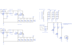
Small dual rail power bus board with (optional) locking connectors and generic slots for Pololu switching voltage regulators.
Headers:
All the header in this board are a generic 100 mil spaced headers, but connector choice can make this project much more worthwhile. The suggested 2 pin header is Molex 70543-0001 or similar. This is a locking, polarized connector. Note that the connectors on one side of the board are flipped 180º from the other side. This is so that the locking tabs are consistently on the inside/outside of the board. The polarity of the connected is determined by how it is installed by the user.
LED Power:
Depending on how stable the input battery power is, you may want to drive the power status LEDs from on of the regulators. This is possible by stuffing R5 or R6 instead of R4. Note that R4/R5/R6 must be mutually exclusive. The values of R7/R8/R9 should be adjusted depending on the led and power source.
Regulator options:
This board should support any of the Pololu 3, 4, or 5 terminal, single sided power regulator modules. The options give a range of 1.8-25V at up to 5A per rail. Only one of the 2 slots on each side should be used at a time. The regulator board will likely need to be installed vertically with a right angle 100 mil header. Depending on the package, you may also be able to use a discrete linear regulator in the provided slots.
All regulator options are at http://www.pololu.com/category/84/regulators-and-power-supplies .
Current protection:
Each regulator rail has it's own fuse for over current protection and a reverse voltage protection FET. There is a spot for either a 3AB/3AG glass fuse or a 0805/0603 poly fuse. This should give a wide range of options (10mA-45A). The RVP FET is currently rated for 230mA. If you opt not to use the fuse, just short the poly fuse pads with a 0 ohm resistor. To disable the RVP FET, short R1/R11 with a 0 ohm resistor.
Mounting:
The board has 3 holes for 4-40 screws. It also has no components on the back, which should make it flat enough to use mounting tape on.
I need more than 2 power rails:
That was an expected use case. Simply put 2 boards in line and connect the battery terminals in series.
I need to use a higher current regulator/need to access the battery power directly:
That was also an expected use case. The extra battery terminals next to the input terminals are meant to power something directly off the battery without splicing. This might be a motor controller or one of the larger Pololu regulators (especially the inline ones with terminals on 2 sides).
Gallery
The project owner hasn't added any images yet.
Design Files
Embed Code
Component (33)
Qty
Description
Capacitor
C13
1
Generic Capacitor (0.1uF)
Electrolytic Capacitor
C6
1
Generic Electrolytic Capacitor (100uF)
testpoint_100_180
TP5, TP6, TP3, TP4, TP8, TP7
6
Testpoint 100 mil hole / 180 mil pad for large gauge connections
2 pin header (non-polarised)
J22, J17, J5, J14, J19, J21, J20, J18, J6, J3, J4, J13
12
2 pin header, 0.1" / 2.54mm pitch, through-hole